From robot acceleration
to the right pump.
How much vacuum do the cups need, how much air leaks away, and which pump and cup hole size keep the carton on the gripper? Five steps, every formula the simulations use, explained simply.
A cup does not pull. The room pushes.
A suction cup holds because the air in the room presses the carton onto the cup harder than the thin air inside the cup presses back. The holding force is that pressure difference times the cup's effective area. So “which pump?” really means: which pump keeps the pressure inside the attached cups low enough, while air leaks in everywhere?
Air leaks in through three doors: loose cups (a cup that missed the carton is an open hole into the chamber), the attached cups themselves (cardboard is porous and the rim is never perfect), and the gripper (seals, fittings). The pump has to carry all of that air away, and the more it has to carry, the less deep the vacuum it can hold.
Load case
Carton mass, robot acceleration and gravity.
→ force the cups must carryRequired cup vacuum
Gripper simulation (MuJoCo) with 0–10 loose cups, worst direction.
→ highest allowed cup pressure puLeak & flow model
Pump curve, hose, chamber, cup holes, carton leak.
→ pu for any pump and hole sizeCalibrate
Fit the unknown leaks on 26 pressure readings of our 17-cup gripper.
→ leak areas and losses we trustChoose
Smallest pump and best hole do that meet the requirement.
→ pump size per number of loose cupsThree ways to say the same pressure
| Name | What it means | Example |
|---|---|---|
| Absolute pressure | Measured from perfect vacuum. Room ≈ 1000 mbar. | 400 mbar abs |
| Gauge pressure | Measured from room pressure (what most dials show). | −600 mbar = −60 kPa |
| Vacuum depth | How far below room pressure, as a positive number. | 60 kPa |
1 kPa = 10 mbar. With the room at 1000 mbar, a vacuum depth of 60 kPa means 400 mbar abs inside the cup.
Holding force of one cup
$$F = (p_a - p_u)\,A_\text{eff}$$\(p_a\) room pressure, \(p_u\) pressure inside the cup, \(A_\text{eff}\) effective area. Our Ø41 mm office cup pulled off at 4.2 kg (41.2 N) at 60 kPa, so \(A_\text{eff} \approx 41.2\,\text{N} / 60\,\text{kPa} \approx 6.9\,\text{cm}^2\) (like a Ø30 mm disc). At 40 kPa the same cup holds ≈ 2.8 kg straight up.
How much vacuum do the cups need?
The load case
The robot may accelerate the gripper at up to 8 m/s² in any direction. The carton has to follow, so the cups must push and pull it with
$$\vec F_\text{cups} = m\,(\vec a + g\,\hat z)$$\(m\) = 15 kg, \(\vec a\) the gripper acceleration (|a| = 8 m/s²), \(g\) = 9.81 m/s². Accelerating straight up is the heaviest pull: 15 × 17.8 ≈ 267 N. Sideways accelerations add shear and tipping moments. The simulator applies this as an extra “gravity” \((-a_x,\,-a_y,\,-g-a_z)\) and holds it for the whole test (conservative).
The cup in the simulation
Each cup is a stretchy, non-linear spring (see part 01). For this study its force scales with the vacuum (a stated hypothesis; only 60 kPa is measured):
$$F(d) = B\,\frac{v}{60}\,\ln\!\left(1+\frac{d}{A}\right),\quad B = 12.79\ \text{N},\ A = 1.372\ \text{mm}$$ $$F_\text{pull-off} = 41.19\ \text{N}\cdot\frac{v}{60}$$\(d\) = stretch of the cup, \(v\) = vacuum depth in kPa. Shear is limited by friction, \(\mu\,(F_\text{pull-off} - T + C)\) with \(\mu\) = 0.5. A cup lets go by pull-off or by peeling (tilting more than 30°); sliding alone never releases it.
The search
- Grips: top grip with one chamber (16 cups, other chamber plugged), and side + bottom at 90° (32 cups) on the end face or the long face of a 600 × 300 × 300 mm carton.
- Loose cups: 0 to 10, starting at the sides. Two orders: symmetric (both sides alternately) and one-sided. The worse one counts.
- Directions: 26 (±X, ±Y, ±Z, edges and corners of a cube), then a finer search around the worst.
- Vacuum: bisection between 1 and 100 kPa to 0.5 kPa.
When is the carton “held”?
| Criterion | Fails when |
|---|---|
| Does not drop | floor contact, all cups released, the carton keeps creeping, or gross sag/tilt (> 100 mm / 30°) |
| Held in place | the same, or sag > 25 mm / tilt > 10° |
Where the air comes from, and where it goes
The vacuum system is a chain. Air enters at the cups and leaks, collects in the chamber, flows through the outlet and the hose, and is removed by the pump. In steady state the same mass of air passes every link each second, so the model balances mass flow \(\dot m\) [kg/s], not volume.
3.1 Air as an ideal gas
$$\rho = \frac{p}{R\,T},\qquad Q = \frac{\dot m\,R\,T}{p}$$\(R\) = 287.05 J/(kg·K), \(T\) = 293.15 K. The same mass flow is a bigger volume at low pressure. “m³/h at room pressure” (\(Q_a\)) is the volume that air had in the room.
3.2 The pump
$$\dot m_p = \frac{p_p\,S(p_p)}{R\,T},\qquad S_\text{scaled}(p) = \frac{S_\text{nom}}{40}\,S_B(p)$$\(S\) is the volume the pump swallows at its inlet pressure \(p_p\), read from the Becker VT 4.40 curve \(S_B\) (section 04). A hypothetical bigger pump keeps the same curve shape and the same 150 mbar ultimate pressure.
3.3 Air through a hole (loose cup, cup restriction, leaks)
\(a\) hole area, \(C_d\) discharge coefficient (how much of the area the jet really uses; ≈ 0.8 for a clean drilled 5 mm long channel), \(\gamma\) = 1.4. In plain words: the lower the chamber pressure, the more air rushes in, until the air in the hole reaches the speed of sound. Below about 528 mbar in the chamber the hole is choked: it lets in a fixed maximum, however hard the pump pulls.
3.4 An attached cup: two holes in series
Air seeps through the carton and along the rim into the cup (an equivalent hole \(a_s\) ≈ 0.35 mm² per cup), and must then pass the cup's restriction hole into the chamber. The cup pressure \(p_u\) settles where both flows are equal:
$$\dot m_\text{seal}(p_a \to p_u;\ a_s) = \dot m_\text{hole}(p_u \to p_c;\ C_d\,a_o)$$A small restriction hole makes \(p_u\) rise far above \(p_c\). This is why a too-small hole hurts the attached cups.
3.5 Hose and outlet losses
$$p_\text{up}^2 - p_\text{down}^2 = \left(f_D\,\frac{L}{D} + K\right)\frac{R\,T}{A^2}\,\dot m^2$$Isothermal pipe flow. \(f_D\) is the Darcy friction factor from the Reynolds number \(Re = \dot m D/(A\mu)\) (Churchill 1977, smooth hose), \(K\) the extra losses of couplings and fittings: hose \(K\) = 41 (fitted), outlet = sharp entry 0.5 + widening \((1 - A_g/A_h)^2\) + 1.8 (fitted).
3.6 Putting it together
$$N_\text{open}\,\dot m_\text{open}(p_c) + N_\text{att}\,\dot m_\text{att}(p_c) + \dot m_\text{bg}(p_c) = \dot m_p(p_p)$$The solver guesses the pump-inlet pressure \(p_p\), walks up through hose and outlet to \(p_c\), adds up all inflows and adjusts \(p_p\) (Brent's method) until inflow equals what the pump removes. The background leak is one equivalent hole of ≈ 4.7 mm². Outputs: every pressure, every flow, and \(p_u\).
Becker VT 4.40, read straight from the datasheet
We have no measured curve for our Wordfik VD40, so its catalogue twin, the Becker VT 4.40 (40 m³/h, 150 mbar, 50 Hz), stands in. The curve was extracted exactly from the vector drawing in the datasheet PDF (page 2), not traced by eye: the red circles below sit on the printed line.
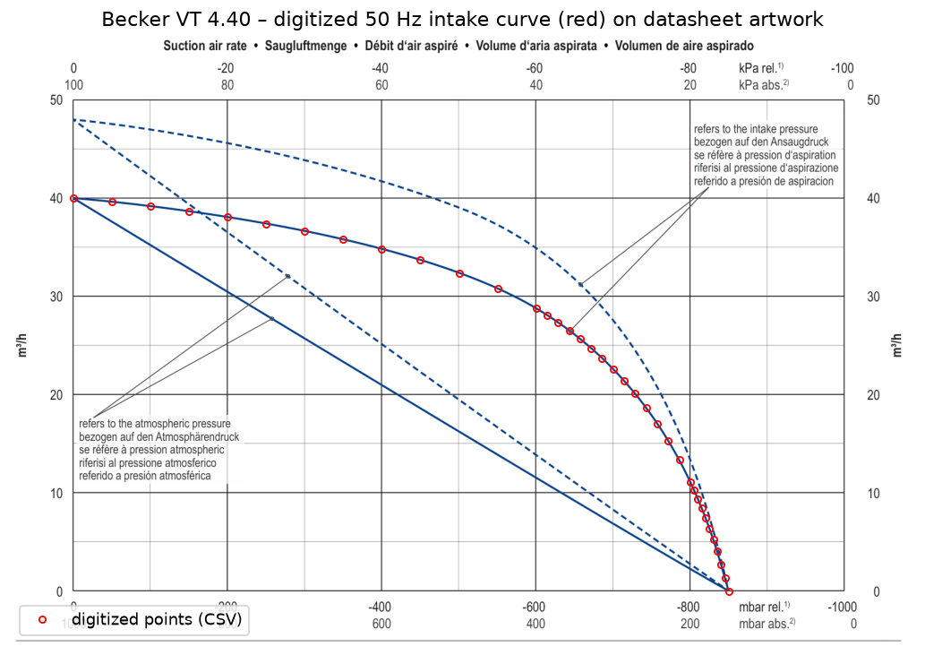
Why two lines? At 400 mbar the pump swallows 28.8 m³/h of thin air, but that air took up only 11.5 m³/h in the room. Leak flows are counted at room pressure, so the lower line is what the pump can “afford” to leak.
What the 17-cup gripper told us
Three gauges (pump inlet, hose start, chamber) were read for 26 configurations of the current 17-cup gripper and VD40 pump:
- A: all 17 holes plugged: shows the background leak.
- B1–B17: 1 to 17 holes open, the rest plugged: open-hole flow.
- C1–C8: cups on a carton, the rest open: the carton/rim leak.
The surprise: to explain the B series, the 2 mm holes would need a discharge coefficient of ≈ 1.8–2.05, which is physically impossible (max ≈ 1). Two explanations fit the data equally well:
- V1 “weaker pump”: the VD40 delivers only ~47 % of the Becker curve.
- V3 “bigger opening” (used here): the printed 2 mm holes pass as much air as clean ≈ 2.9 mm holes.
V3 is favoured because the holes are 3D printed (prone to oversize) and because V1 would need an implausibly large hose loss (K ≈ 223). A free-air flow test on the pump or a drill-shank check of the holes decides it for sure.
| Quantity | Value |
|---|
Fit quality on the measured pressures: about 8 mbar rms. Hold-out cases C3/C5/C7: 12–32 mbar.
Why the hole size has a sweet spot
Holes too big: every loose cup dumps a lot of room air into the chamber, so the chamber pressure rises. Holes too small: the air that seeps into an attached cup cannot get out fast enough, so the pressure inside that cup rises, and that is the pressure that holds the carton. In between lies the best hole. It moves to smaller holes when more cups are loose, and slightly larger with a bigger pump.
Show as a table
| Pump | Best hole | pu at best hole | pu with today's holes |
|---|
Required vacuum and pump, per grip and loose cups
Smallest pump (Becker shape, scaled) that keeps the attached cups at or below the required pressure, with the best of the listed hole sizes (today's, 2.5, 2.0, 1.75, 1.5, 1.25, 1.0 mm). “—” = not held at any vacuum in the gripper simulation; “> 280” = no pump up to 280 m³/h reaches it.
• Side + bottom, long face: easy. 17–36 kPa is enough; about 35 m³/h with 1.25 mm holes survives 10 loose cups.
• Side + bottom, end face: 39–74 kPa. With 1.5 mm holes, 41 m³/h covers 4 loose cups and about 90 m³/h covers 7; 9 or more loose cups need more than any pump up to 280 m³/h.
• Top grip with one chamber: 45–72 kPa for 0–4 loose cups (54 m³/h covers 3 loose with 1.5 mm holes); with 5 or more loose cups on one side the carton is not held at any vacuum.
Full tables per hole size, numerical checks and assumptions: PDF report ↗.
What is assumed, and what to measure next
- Cup force and stiffness scale with vacuum: a hypothesis; only 60 kPa is measured.
- Rigid carton, fixed gripper, acceleration held for the whole test (conservative for slow sliding).
- All attached cups share one vacuum level; loose cups are open holes.
- Pump = Becker VT 4.40 shape (model V3); bigger pumps are scaled copies with the same 150 mbar limit.
- The 32-cup gripper is extrapolated from the 17-cup measurements; the background leak is kept constant.
- Results are thresholds. Add a margin (e.g. +20 % force ≈ 1.2 × the required vacuum) before buying.
- Not a lifting-safety certification.
1. Gauge the printed holes with drill shanks (does 2.5–2.9 mm fit?).
2. Free-air flow of the current pump (≈ 40 m³/h means V3).
3. Pressure inside one attached cup, before and after re-drilling.
4. Held / not-held test at one or two vacuum levels, measuring the carton sag.